01CRT monitorsCathode ray tube (CRT) displays are large and bulky and have been widely replaced commercially by digitized liquid crystal displays (LCDs). However, CRTs are still very important in vision science research.
CRT monitors
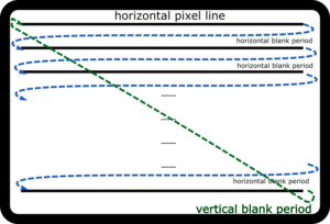
CRT displays consist of a layer of phosphor, an organic material that glows briefly when an electron gun inside the display fires an electron beam. The beam rapidly scans the display from left to right, top to bottom, in a pattern known as a raster. At the end of each line, the electron beam stops briefly and then jumps back to the start of the next line. This is called the horizontal fading period. When the gun reaches the bottom of the screen, it jumps back to the top of the screen and begins the next frame of the display.In analog video signals, the signal that causes the electron gun to jump back to the top of the display is known as the vertical sync pulse. This pulse is also included in digital video communication protocols, and it effectively marks the beginning of the next frame of the video signal. Video synchronization will be discussed in depth later.
Raster mode for CRT displays
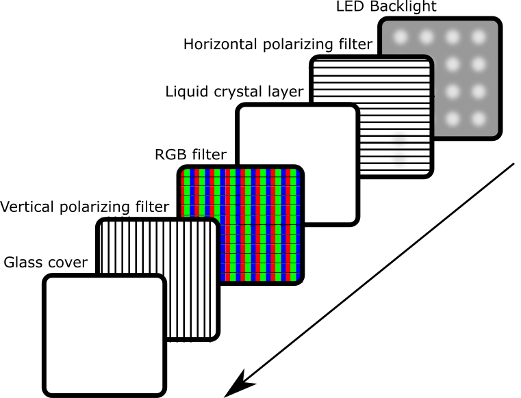
Commercial LCD panels are not illuminated in raster mode. Instead, they have a grid of pixels that are simultaneously illuminated by a backlight. The light shines through a filter that blocks all non-horizontally polarized light. The light then passes through a liquid crystal layer, where molecules rotate the polarization of the light between 0-90 degrees. The degree to which a molecule rotates light depends on its structure. An electric current can change the structure of the liquid crystal molecules, thus changing the angle of polarization.After light passes through the LCD layer, a red, green, and blue filter limits the output spectrum to light of a specific color. A second filter allows only vertically polarized light to pass through the display, which means that any light that has not been altered by the liquid crystal layer (e.g., still horizontally polarized) will not pass through, and the pixels will be completely dark.
Layer structure of LCD display
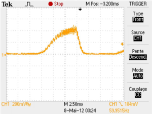
Whenever we change the value of a single pixel on a display, we must change the structure of the molecule responsible for the RGB intensity of that pixel. Depending on the display, it can take several milliseconds for the molecules on the panel to completely stabilize in a new position. The time it takes for a single pixel to stabilize is called the pixel response time.Typically, the backlight of an LCD display is always on, which means that as the liquid crystal molecules change structure, the display shows a complete change in pixel brightness. On a typical LCD, this ramp can last about 5 milliseconds, transitioning from black to white, and can be seen in the photodiode record shown below.
Pixel Brightness Variation of VIEWPixx Displays in Conventional Backlight Mode
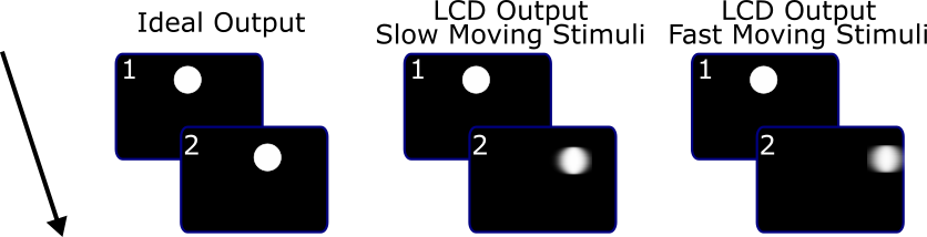
A very slow pixel response means that the pixel conversion lags behind the speed of the video signal. This causes the image to drag between frames, a phenomenon known as "ghosting".
LCD monitor ghosting
Another consequence of slow pixel response is motion blur. Especially for high-contrast, fast-moving objects, pixel stabilization lags behind the speed of movement. As a result, the edges of moving objects blur.
motion blur phenomenon
These display artifacts are not ideal for visual scientists looking for tightly controlled stimuli, especially high-contrast moving stimuli.The progressive scanning mode of CRT monitors, on the other hand, does not produce the aforementioned ghosting and blurring artifacts, which is why CRT monitors have been used for research in vision science. However, CRT monitors have their own limitations, notably excessive size, increasing difficulty in purchasing, and limited refresh rates (usually less than 75 Hz).To meet the needs of modern displays, VPixx has developed a high-resolution, 120hz LCD monitor with a scanning backlight mode that mimics the raster mode of a CRT monitor.
Scanning backlight technology
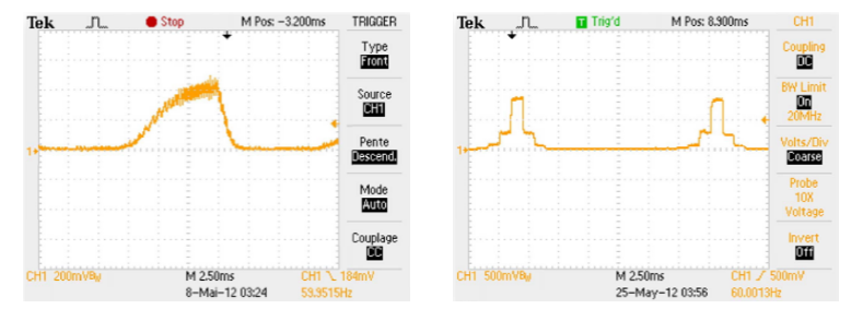
Using scanning backlighting technology, individual pixels are not illuminated until the liquid crystal molecules are almost completely stabilized. The result, visible to the naked eye, is cleaner frame transitions with minimal ghosting and motion blur.The image on the left below shows the brightness of a single pixel during the transition from black to white to black without the scanning backlight mode enabled. The rise time to peak brightness is 5 ms and the fall time is 1 ms. The image on the right shows the change in brightness of a pixel (black-white-black-white-black) with the backlight on. Here, the rise and fall times are both 1 ms.
Pixel Brightness Variation of VIEWPixx /3D Displays with Scanning Backlight Mode Off and On
02LCD TechnologyWe've covered the basics of how LCDs work, but not all LCDs are created equal. In this section, we'll discuss the different LCD technologies and focus on how they affect the overall display.
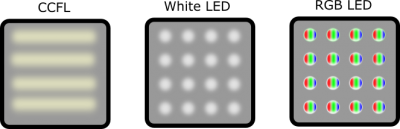
2.1 Backlight technology: fluorescent, white lightLEDwithRGB LED
Different backlight sources
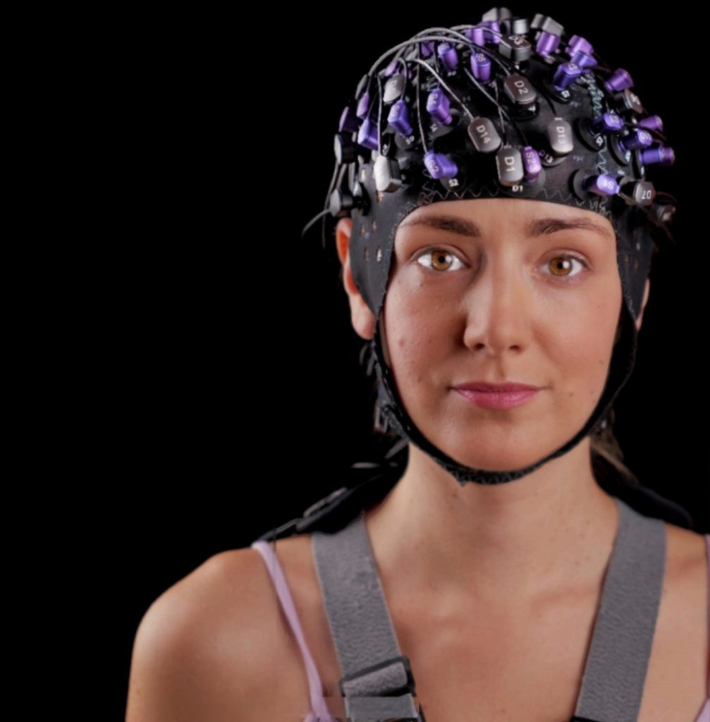
The light source used in the LCD backlight has a significant impact on the color gamut, brightness and color uniformity of the display.Older consumer LCD panels typically used cold cathode fluorescent lamps (CCFL) as a backlight source. While not expensive, this light source tends to produce a relatively narrow color gamut, which can make colors appear somewhat faded in the viewer's eye.CCFL panels also have relatively poor display brightness and color uniformity (<80%) and are prone to hot spots.With the rise of reliable light-emitting diodes (LEDs), many high-end lcds have begun to use LED backlighting to take advantage of their wider color gamut, better contrast, and greater energy efficiency.LED backlighting can be white, or a mixture of RGB LEDs to produce a broad spectrum of white.In general, RGB LEDs produce a wider color gamut than white LEDs. Both types of backlighting can be calibrated for uniform display brightness. And RGB LED displays can be factory calibrated to the industry-standard white point, ensuring uniform color throughout the display.The VIEWPixx /EEG uses a white LED backlight, while the VIEWPixx and VIEWPixx /3D use RGD LEDs. all three displays are >95%. the VIEWPixx /EEG has a color uniformity of approximately 90%. the VIEWPixx and VIEWPixx /3D are factory-calibrated to D65 industry standard white point and have >95% color uniformity across the panel.
2.2 Panel Technology: Twist to Column and Flat Conversion
The structure and behavior of the liquid crystal molecules in an LCD also have an impact on display performance. Specifically, the layout of the molecules affects their color fidelity, contrast, and viewing angle. The behavior of the molecules also determines the response time of the pixels.The two main LCD panel technologies are Twisted Nematic (TN) panels and In-Plane Switching (IPS) panels.TN panels have a relatively fast pixel response time (~5ms, black → white → black). This means that TN panels are able to synchronize with the fast movement of the VIEWPixx scanning backlight.Both VIEWPixx /3D and VIEWPixx /EEG use TN panels. However, TN panels have a rather small viewing angle, which means that colors and brightness can change dramatically when the monitor is viewed from the side.In contrast, IPS uses a parallel molecular structure in the LCD layer to maintain richer colors over a wider range of viewing angles.However, IPS panels are slow (pixel response time ~7 ms). This stabilization time can lag behind scanning backlighting, which can lead to ghosting, so we don't recommend using IPS monitors with scanning backlighting mode.VIEWPixx uses an IPS panel and is therefore better suited to presenting rich still color images.
2.3 depth (archaic)
A digital video signal converts color information into a binary signal. The bit depth of a monitor is the number of color layers that can be transmitted and displayed on the screen. The higher the bit depth, the more color layers that can be used, and the finer the gradient between colors or gray values displayed in the image.
Display effect of different bit depths, from left to right: low to high
A typical screen uses 8-bit RGB colors, where full white is represented by the RGB color triad [255,255,255]. This means that the user can make black and white adjustments in 256 binary steps (0-255). In comparison, 10-bit color divides the same color space into 1024 binary steps, and 12-bit produces 4096 binary steps.All three VIEWPixx use 8-bit color by default. both VIEWPixx /3D and VIEWPixx have special color modes that allow the user to display images at higher bit depths. the VIEWPixx /3D supports up to 10-bit, while the VIEWPixx with IPS panel technology supports up to 12-bit.
03Digital I/O and SynchronizationOur VIEWPixx series is more than just a screen. All three displays have built-in hardware for data synchronization. In this section, we will detail some of these features.
3.1 Zero image processing and defined video rendering time
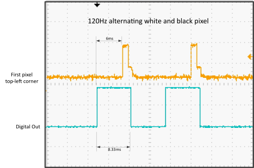
All three VIEPixx receive video signals directly from your computer's graphics card via a Dual-Link DVI (Dual-Link DVI) interface.The vertical synchronization pulse mentioned in the previous CRT section is also present in the DVI video protocol. When your monitor receives a full frame of video data, it will follow a vertical synchronization signal immediately after that frame of picture data. At 120hz, each frame output by the video card does not go into our monitor's buffer for preloading; instead, they are displayed immediately. This means that the time between the reception of the vertical synchronization pulse and the lighting of the screen is completely defined. In other words, using vertical synchronization pulses, we can determine with microsecond precision when an image actually appears on your monitor.When scanning backlighting is enabled. The time between the vertical synchronization pulse and the stabilization of the upper left pixel of the display (the first pixel scanned in the CRT raster) is exactly 6 milliseconds.
Time difference between the digital TTL signal (synchronized output when receiving the vertical sync pulse) and the brightness of the upper left pixel
Our hardware can be programmed so that the vertical synchronization pulse also triggers the generation of the output signal. On the VIEWPixx /EEG, this triggering is entirely driven by Pixel Mode.VIEWPixx and VIEWPixx /3D can be configured to send customized trigger signals for digital, analog or audio channels. Vertical synchronization pulses can also be tagged to the on-board system clock and used to associate incoming data (e.g., from a key box or third-party recording system) with the moment of presentation of the visual stimulus.
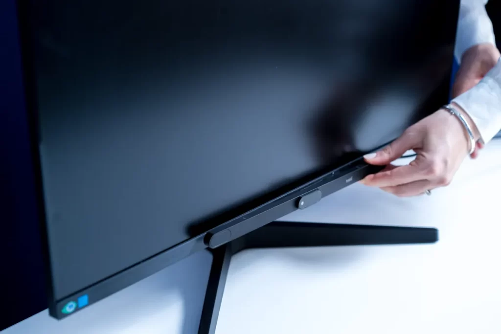
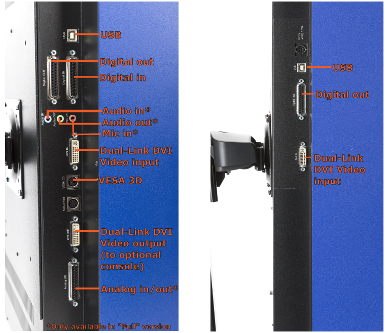
3.2 I/OConnections:Full vs.itesystems
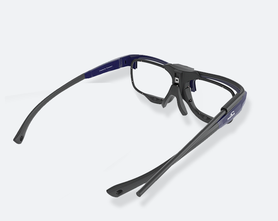
The VIEWPixx and VIEWPixx /3D provide a full on-board I/O interface similar to the DATAPixx2. The Lite versions of both displays provide digital inputs and outputs on two DB25 ports. There is also a VESA-standard 3D port for IR emitters and active 3D shutter glasses.Although VIEWPixx also has a 3D interface, we only recommend using VIEWPixx /3D for 3D rendering because TN screens are better suited for fast transitions with minimal crosstalk.The Full version of the VIEWPixx and VIEWPixx /3D includes all the features of the Lite system and supports analog I/O on a third DB25 port (4 channels digital to analog, 16 channels analog to digital.) The Full version also includes three 25mm jacks for audio in, microphone in and audio out.The VIEWPixx /EEG has digital output capability on a single DB25 connector. This interface can only drive digital outputs via pixel mode.
Left: VIEWPixx and VIEWPixx /3D; Right: VIEWPixx /EEG
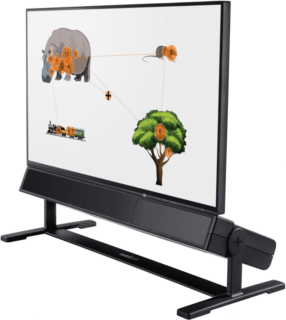
3.3 Main test monitor output
VIEWPixx and VIEWPixx /3D have a dual-link DVI outputThe video signal can be sent to an optional second monitor for easy viewing by the primary test subject.Importantly, the copying of the video signal occurs after the video signal has been sent from the graphics card, which means that no additional workload is added to the graphics card and display time is not affected.
3.4 Programming control
VIEWPixx and VIEWPixx /3D can be programmed and controlled using the MATLAB/Psychtool or Python toolkit provided with VPixx for data synchronization and data acquisition. VIEWPixx /EEG is not supported.
Attachment:
VIEWPixx Series Parameter Comparison Table
VIEWPixx
VIEWPixx /3
VIEWPixx /EEG
population (statistics)
pertain
Static display with rich colors and fine gradients
Highly dynamic, high contrast motion stimulation, 3 d stimulation
Highly dynamic, high contrast motion stimulation
resolution (of a photo)
1920×1200
@120 Hz
1920×1080
@120 Hz
1920×1080
@120 Hz
response time
1-7ms
1ms
1ms
Scanning backlight
Optional, not recommended
Optional, recommended
default (setting)
LCD technology
do sth. with one's back to the light
RGB LED
RGB LED
white LED
kneading board
IPS
TN
TN
depth (archaic)
Default 8 bits, maximum 12 bits
Default 8 bits, maximum 10 bits
8-bit
color gamut
spread
spread
moderate
one degree of color uniformity
95%
95%
90%
luminance uniformity
95%
95%
95%
Factory D65 white point calibration
be
be
clogged
Data I/O and Synchronization
Digital I/O
Digital Inputs and Outputs
Digital Inputs and Outputs
Digital output (vertical sync trigger signal only)
Analog I/O
Full version
Full version
not have
Audio I/O
Full version
Full version
not have
MATLAB/
Python
Software Support
be
be
clogged
This article comes from the WeChat public number: EVERLOYAL


